Procedural Benchmarks For Common Fabrication Detail
A summary report of the FENet Education and Dissemination (E&D)
workshop in Majorca, Spain, 25th March 2004.
 By Dr. Jim Wood, University of Strathclyde, UK
This article provides a summary of the observations made at the
Education and Dissemination session in Majorca, which was
reasonably well attended and resulted in 3-4 hours of stimulating
discussion.
The three procedural benchmarks are shown below.
Results obtained from all contributors are available for download
for each benchmark, as well as results and the benchmarks
themselves. The following observations are based on the results
contained in these spreadsheets and also from the more
comprehensive submissions made by participants.
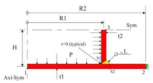
Fig. 1 Procedural Benchmark FENET_E&D1 “Shell
Intersection”
Benchmark Download (PDF)
Results Download (PDF)
Local Stresses
Stiffness, Overall, Field
Presentation Download (PDF)
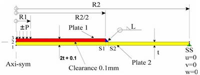
Fig 2 Procedural Benchmark FENET_E&D2 “Shell
Reinforcement”
Benchmark Download (PDF)
Results Download (PDF)
Local Stresses
Field Stresses
Stiffness & Overall Stresses
Presentation Download (PDF)
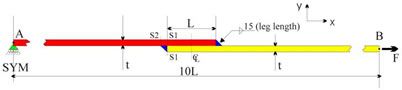
Fig. 3 Procedural Benchmark FENET_E&D3 “Offset Shell
Mid-surface”
Benchmark Download (PDF)
Results Download (PDF)
Local Stresses
Stiffness, Overall & Field Stresses
Presentation Download (PDF)
Generic observations
1.
Significant variation in the modelling, results, assessment and
conclusions relating to fitness for purpose of such detail is
apparent across analysts and industry sectors, for both static and
fatigue situations.
2.
Human error is apparent, including:
a. Mis-interpretation of boundary conditions;
b. Incorrect use of finite element functionality that altered
physical response;
c. Reporting wrong results;
d. Using stress output directly at singularities;
e. Using averaged stresses at shell intersections.
3.
Lack of “engineering common sense” is apparent. For
example, not all contributors checked that the field stresses
compared well with hand calculations, where appropriate.
4.
From this limited linear elastic exercise:
a. The need for finite element knowledge is confirmed;
b. The need for general engineering education is confirmed;
c. The need for industry specific knowledge is confirmed;
d. The need for validation is confirmed;
e. The need for adequate QA procedures is also confirmed.
5.
Established “common best practice” across the various
industry sectors is not apparent.
6.
Various guidelines exist for weld modelling and assessment in few
industry sectors.
7.
Use of experimentally derived results on real weld geometries is
recognised as a necessary part of the assessment process for
fatigue. It is how FEA results are obtained (often at locations
where singularities exist) that provides variations in approach.
8.
As with all analyses, the adequacy of any idealisation must be
judged in terms of the purpose of the analysis being conducted. The
idealisation of such fabrication detail will affect static and
fatigue (and dynamic, buckling, limit and fracture assessments) to
different degrees.
9.
The influence of fabrication detail can be local or global in
nature and this fact should be considered when judging adequacy.
The details selected for consideration as “procedural
benchmarks” have both local and global measures selected as
targets and all showed variation.
10.
It is possible to use shell models to obtain necessary stress data
for fatigue assessment of such details, but care and understanding
is necessary. It should also be recognised that shell models will
produce finite converged results at intersections.
11.
There would appear to be two distinct approaches to obtaining
“hot-spot” stresses from finite element models:
a.
A stress linearization procedure (not required with shell
representations), designed to remove the peak stress component and
leave the membrane and bending stress components. Such an approach
will include gross geometric stress concentration effects. Some
finite element systems provide post-processing tools for defining
the “assessment section” in both 2D and 3D
representations and for linearising the results. This approach is
common in the Pressure Vessel industry.
b.
A number of “extrapolation” approaches, with
slight variations in the extrapolation procedures, are in use.
These approaches invariably involve element sizes of the order of
0.4t and differ in whether linear or quadratic extrapolation is
used to the hot-spot location (which is often a singularity in
nonshell models). Some of these procedures also provide details of
how the stress distributions from shell models should be displaced
by up to half a shell thickness (depending on the angle of the
intersection), before extrapolating to the hot-spot. However, it is
recognised that specific Codes of Practice may not give the analyst
any choice in which procedure to adopt.
12.
Some fatigue assessment procedures require the use of the stress
range on the weld throat area. Stresses plotted across the throat
will show a highly non-linear variation. Although not always clear,
it is likely that an average value of stress is required from the
results, to provide consistency with hand calculations. Although
not always clear, it is likely that a simple ‘membrane +
bending’ value of stress, with peak component removed, is
required from the results, to provide consistency with hand
calculations.
13.
Some analysts used thick shell elements. The fact that most did
not, would perhaps indicate that participants from different
disciplines do not have a common understanding of when plates and
shells become thick.
14.
Given the nature of the Displacement Finite Element Method and the
details examined, it is perhaps not surprising that greatest
agreement is apparent for global stiffness ( as measured by overall
displacements), closely followed by field stresses (by definition
away from local stress concentrations). Greatest variation is
apparent for local stresses, which include finite values derived
from distributions in the vicinity of singularities. In addition,
as would be expected, greatest variation is apparent for very small
target values, with best agreement generally for large values.
Preliminary observations for E&D1
1. For this detail, the practice of displacing shell stress
distributions by half a shell wall thickness before interpolating
values at the “notional” position of weld toes
(hot-spot), would seem unnecessary.
2. The various results provided by “Analyst Identifier
1” show remarkably little variation amongst 2D-Axi and shell
models (with and without weld representation). Whilst inclusion of
the weld stiffness (by whatever means) improves the comparison with
the highly refined 2D-Axi results, it is not apparent that this
additional complexity is merited over a simple shell representation
and use of stresses at the location corresponding to the weld toe.
3. Although not considered in these benchmarks, it is noted that a
simple shell intersection representation already has too much mass,
without the addition of any measures designed to include the effect
of the weld. This will have some bearing on dynamic analyses and
weld models will result in a greater need to reduce the density of
local elements for accurate representation.
Preliminary observations for E&D2
1. The reason for the large variation in contact radius results for
load case 2 is not apparent. This is clearly a function of global
stiffness representation as well as the effectiveness of the
contact methods used. Given the relatively good agreement on
overall deflections in most cases, it must be assumed that the
differences are largely due to the contact methods. This fact
emphasises the need for adequate contact benchmarks.
2. The various results provided by “Analyst Identifier
1” show remarkably little variation amongst D-Axi and shell
models for deflections, field stresses and weld-toe stresses, for
load case 1. The poor comparisons for load case 2 are due to the
lack of contact simulation in the shell model for load case 2.
3. Assuming the reinforcing plate to be integral did not provide
good agreement for field stresses at the plate centre. The
comparison of local stresses in the region of the weld are
reasonable, particularly for those of larger magnitude. It is clear
therefore, that if such an assumption is to be made, then care must
be taken to ensure that both plates effectively act as one through
use of a suitable number of spot or puddle welds. The results
for the “central spot-weld” idealisation, would
indicate that an “integral” behaviour may be possible
with relatively few plate connections.
4. Neglecting the offset due to the reinforcing plate and assuming
a double thickness integral representation over the reinforced area
produced similar results to the “integral” idealisation
with offset.
Preliminary observations for E&D3
1. Only two participants showed that the problem was large
displacement (subsequently confirmed by the coordinator), in spite
of the tip deflection being less than the thickness of the plate.
Reductions in deflections and stresses are significant. The rules
of thumb commonly used as a guide to when large displacement
effects become significant for beams, plates and shells are clearly
not applicable for this problem. The reason for this is apparent
when the source of the non-linearity is given due consideration.
2. 3D models (shells and bricks) show variations in results across
the width, which are obviously absent from 2D results. Not all
contributors commented on this effect.
3. Neglecting the offset, even with correct plate thicknesses,
fails to predict adequate values for overall stiffness, field
stresses and local stresses. Analysts should therefore think
carefully before neglecting offsets in plate/shell mid-surfaces, as
their effects can have a global nature as well as local. For
thinner plates/shells, large displacement effects may act to reduce
the global effect of the offset, through local bending of the joint
and effective realignment of the midsurfaces.
4. The modelling of contact between the lapped plates appears
irrelevant for the relative joint sizes considered. The results for
separate plates, with and without contact, and models where the
plates were assumed integral appear similar. The latter model
however, fails to pick up the stress singularity that exists at
either end of the lap running between fillet weld roots. Almost all
contributors failed to highlight this singularity, in any model.
Closure
The general consensus of those participating was that this was a
worthwhile exercise, that should be of interest to the wider FE
community. Given the level of participation, this fact was clearly
not always recognised. It should be recognised that the relevance
of the general observations clearly have broad interest to the
entire finite element community, it should also be recognised that
the relevance of the detail of the modelling strategies used is not
confined to those involved in welding 15mm thick steel plate! It is
now my task to try and pull together some sort of conclusions from
this exercise. To this end, I have asked contributors to have a
look at the final collated results and take the opportunity to
comment on the results that they provided in relation to the rest.
In addition, they have also been asked to have a look at the
preliminary observations and to comment on these and add their own
if necessary.
On receipt of everyone’s comments, I will then document the
exercise. The final document is likely to consist of several
parts…. An Introduction providing the background and aims of
the project; the Procedural Benchmark Specifications; the
“Round- Robin” results (with anonymity maintained);
observations from the exercise and finally some conclusions
regarding good and bad practice in the analysis and assessment of
such details.
This final report is now available to download, as well as being
available from NAFEMS in hard-copy format.
The download is available in a
lo-res PDF format (1.8MB),
as well as a hi-res format, in a zipped package (22MB).